Will Silicon-Based Anode Technology Take the Crown as the Future of High-Energy-Density Lithium Batteries?
Deep Dive Analysis of the Amprius SiCore™ SA-08 Battery
Introduction
The most used anode material for LIBs is graphite which has a specific capacity of 372 milliampere hours per gram (mAh/g). However, the energy density of LIBs can be improved with the incorporation of Silicon (Si) instead of graphite. Si features a high theoretical specific capacity of 4200 mAh/g Li15Si4, which is more than 10 times higher than the traditional graphite anode [1].
However, there are challenges in using Si as it is prone to significant volume expansion and contraction during charge and discharge cycles. This volume changes can cause cracking of the active materials, an unstable solid electrolyte interface (SEI) peeling off from the current collector which eventually leads to electrode failure. Additionally, Silicon based anode suffer from low columbic efficiency, low areal capacity and high materials cost. These challenges have prevented Si from being broadly used in commercial rechargeable LIBs. To overcome these problems, silicon oxide and silicon composite materials are proposed to be used as anodic material as we discuss in the following [1,2].
Silicon Oxide
In contrast to pure silicon, silicon oxide (SiOx, where 0 < x < 2) experiences less volume expansion during cycling than pure silicon, while still offering three times the capacity of graphite. However, using SiOx presents challenges, such as lower electrical conductivity compared to metallic silicon and capacity loss due to the formation of SEI layers. The lower electrical conductivity increases the cell’s internal resistance, which affects its power handling capabilities. Additionally, the continuous growth of the SEI layer reduces the battery’s cycle life.
Silicon Composite
One promising approach to developing a stable, high-capacity anode is to leverage the stability of graphite and combine it with the high capacity of metallic silicon or SiOx-based materials to create a composite anode. In this method, metallic silicon or silicon oxide is embedded in a carbon matrix to buffer the volume changes of silicon. Additionally, composite carbon networks enhance electrical conductivity while providing adhesion and increased chemical stability. Other approaches, such as silicon nanowires, carbon coatings on silicon particles, or 3D structures, contribute to the development of highly silicon-enriched anodes. In silicon-based compositions, volume expansion/contraction, mechanical stress, and electrode pulverization during lithiation and delithiation cycles are major concerns when designing a cell with high cycle life (>1,000 cycles), and these issues are heavily influenced by the silicon content. Regarding production costs, the production of silicon composites is higher than that of graphite, metallic silicon, and most SiOx.
Current Technologies in The Market
In the market, most companies are focused on developing silicon composites using various technologies. The table below compares the technologies used by major companies, along with their claimed performance and applications as of 2024 [2].
| Company | Silicon Content | Technology | Claimed Performance | Targeted Application | Partnership |
|---|---|---|---|---|---|
| Sila Nanotechnology | 50% | Si dominant porous microparticles with a rigid carbon shell | 800 Wh/L | EV, Consumer Electronics | Mercedes, Whoop, CATL, TDK, Samsung, Panasonic |
| Enevate | 70-100% | Silicon microparticles up to 40um with a SiC/carbon shell | 350 Wh/kg, charge in 5min to 75% | EV, Consumer Electronics | RNM Alliance; LGES, Samsung |
| Enovix | 100% | Si particles coated in thin metal-semiconductor layer, 3D cell architecture | 900 Wh/L , 297 Wh/kg | Consumer Electronics | Intel, Qualcomm |
| Amprius | 100% | Si nanowires | 435 Wh/kg, 1200 Wh/L, 1000 cycles | Defense, EVTOL1 | Airbus, US Army |
| Group14 | 50-100% | Elemental Si impregnated in an activated porous carbon scaffold towards pure Si anode | 370 Wh/kg, 1,000 Wh/L | EV, Consumer Electronics | Porsche, ATL(TDK), BASF, Showa Denko, SK |
| IONBLOX | Elemental Si and SiOx nanoparticles wrapped in carbon matrix, with metalcoating | 305 Wh/kg, 640 Wh/L | EVTOL | Applied Materials, Lilium | |
| Nexeon | 80% | Si nanoparticles wrapped in silicon oxide, silicon carbide shells | 400-450mAh/g | EV, Consumer Electronics | WACKER, SK Chemicals |
| OneD | 5% to 50% | Si nanowires grown inside graphite using Cu catalyst to control size | 3250 mAh/g of Si Nanowires | EV | GM Ventures, Volta Energy Technologies |
| Storedot | Metal coated Si nanoparticles with conductive matrix materials | 5-min extreme fast charge | EV | BP, EVE, Daimler, Vinfast,Samsung, TD | |
| Advano | 5-75% | Si nanoparticles with functionalized surfaces produced from scrap silicon | 350 Wh/kg at $90/kWh | EV, Consumer Electronics, ESS2 | Mitsui Kinzoku |
| Leydenjar | 100% | Porous Si anode grown on the Cu substrate via PECVD | 450 Wh/kg 1350 Wh/L | Defense, EVTOL | EIB |
| Coreshell | 60-90% | Micron-sized Metallurgical Silicon. No Silane. | 30% GED and VED Gain, 750+ cycles | EV, Mobility | Zeon, Meyers Manx |
| Ionic Mineral | 80-100% | Continuous Metallothermic Reduction of Silica to Si nanotubes starting with HalloysiteFeedstock | All Si electrode 3200 mAh/g, 85% ICE 2500 mAh/g stable, Si/Gr Blend 15% Si substitution of Gr 750mAh/g 91% ICE 700 mAh/g Stable capacity | EV,Consumer Electronics, Military |
1 Electric vertical take-off and landing
2 Energy Storage System
Table 1: Companies working on developing silicon composite anode material with their technology, claimed performance, target applications and industrial partners as of 2024.
Based on this table, the claimed energy density from most companies ranges from 800 Wh/L to 1,350 Wh/L (290 Wh/kg to 450 Wh/kg). The highest energy densities are claimed by Lyden Jar and Amprius, at 1,350 Wh/L (450 Wh/kg) and 1,200 Wh/L (435 Wh/kg), respectively.
These claimed energy densities indicate that silicon composite-based anodes are a promising technology for future cells. The gravimetric and volumetric energy densities of silicon composite-based anodes are higher than those of graphite-based anodes and lithium-sulfur batteries and are comparable to most solid-state and liquid-based batteries with lithium metal. For example, a solid-state battery with lithium metal and nickel manganese cobalt aluminum oxide (NMCA) can achieve 1,200 Wh/L (500 Wh/kg). The figure below compares different technologies for current and emerging lithium-ion batteries [3,4].
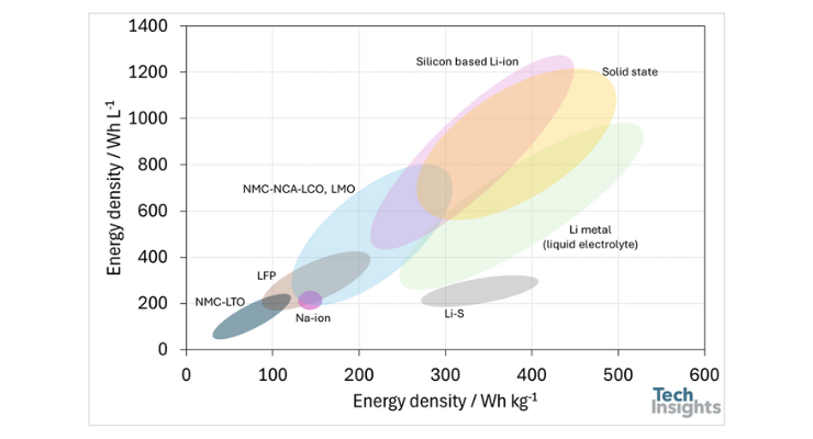
Figure 1: Visual representation of gravimetric and volumetric energy density of the different battery technologies.
Commercially Available Products
These companies are working with investors and partners to develop their products. In late 2021, Sila Nanotechnology introduced its first product, used in the Whoop 4.0 fitness tracker. At that time, we analyzed the battery (WS-40) from the WHOOP 4.0 as part of the TechInsights Battery Essentials subscription. Our results showed that Sila’s anodic material is superior to other silicon-graphite composite anodes, which can lead to improved cycle performance (Sila Nanotechnologies WPH-WS40 (Whoop 4.0) Silicon-Anode Lithium Ion Battery Essentials). Based on our analysis, we confirmed that Sila Nanotechnologies' approach is to mitigate the expansion and contraction of silicon volume through a carbon-based network.
Other products are currently entering the market, and TechInsights plans to perform analyses as they become available.
In January 2024, Amprius introduced its new SiCore™ product platform, expanding its portfolio of industry-leading silicon anode batteries aimed at transforming electric mobility. Along with this launch, Amprius rebranded its existing silicon nanowire platform as SiMaxx™, which includes its current product line, offering up to 500 Wh/kg and 1,300 Wh/L in energy density. The SiCore batteries feature a cutting-edge, proprietary silicon anode material system that delivers high-energy-density performance, surpassing today's graphite cell technology. This new silicon anode chemistry is designed to provide energy densities of up to 400 Wh/kg and a long cycle life, with the ability to endure up to 1,200 full discharge cycles [5].
In this report, we focused on the Amprius SiCore™ SA-08 battery, which is optimized for power-based applications. This battery has a capacity of 11,050 mAh (37.57 Wh). The volumetric and gravimetric energy densities of this battery are 800 Wh/L and 360 Wh/kg (at 30% SOC). In this blog, we briefly review a few key aspects of the Amprius SA-08 battery. A detailed structural and materials analysis of this battery is presented in the Battery Cell Essentials, entitled SA08-Amprius Silicon Anode (SA08-Amprius Silicon Anode Battery (Upgrade Energy -440W 32A battery pack)), while cell performance is reported in the Battery Cell Characterization, entitled (SA08-Amprius Silicon Anode Battery (Upgrade Energy -440W 32A battery pack)).
Electrochemical and Material Characterizations of Amprius SiCore™ SA-08 Battery
Overview of Amprius SA-08
Figure 2 shows the Amprius SA-08 battery. The battery has a pouch cell design (with an aluminum casing laminated with polymer), and the tabs are located on one side. The key features of this battery, taken from the company’s datasheet [6], are listed in Table 2.
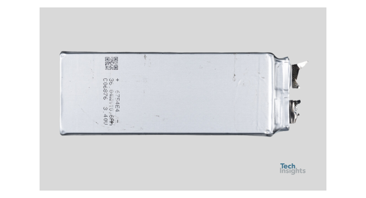
Figure 2: Optical image of the Amprius SA-08 battery.
The maximum charge and discharge voltage of this battery is similar to graphite-based batteries that use Nickel Manganese Cobalt oxide or Nickel Cobalt Aluminum oxide as cathodic material. However, the nominal cell voltage of the Amprius SA-08 battery is lower due to the gradual voltage drop at higher depths of discharge (DOD).
According to the table, this battery features a high discharge rate (5C continuous and 8C pulses), indicating low internal resistance, which we will test in the next section. The operating temperature range is similar to most lithium-ion batteries. In terms of cycle life, the battery has a relatively low cycle life of 300 cycles if fully discharged (DOD = 100%). However, reducing the DOD to 30% significantly improves cycle life. This difference in cycle life can be attributed to the large volume expansion and contraction during lithiation and delithiation at high depths of discharge.
Regarding gravimetric and volumetric energy densities, we compare the Amprius SA-08 battery with the batteries of the Chevy Bolt (first generation), Tesla Model 3 (2019), Tesla Model Y (2022), Hyundai IONIQ 5 (2023), the Welion 22,000 mAh semi-solid-state battery, and the battery in the Whoop 4 (WS-40) in Figure 3.
| Capacity | Typical Minimum |
11050 mAh (37.57 Wh) 10800 mAh (36.72 Wh) |
| Cell Voltage | Nominal Charge cut-off Discharge cut-off |
3.4 V 4.2 V 2.5 V |
| Discharge Current | Max Continues Max Pulse (< 30 Sec) |
54 A (5C) 86.4 A (8C) |
| Charge Current | Typical Maximum (0% to 100% SOC) |
2.16 A (C/5) 32.4 A (3C) |
| Temperature Range | Discharge Charge Storage |
-20 to 60 ˚C 0 to 60 ˚C -20 to 45 ˚C |
| Cycle Life | +1C/-3C, Depth of Discharge 100%, State of Health of 80% +1C/-3C, Depth of Discharge 70%, State of Health of 80% |
300 700 |
| Weight | 106.5 ± 2 g | |
| Dimension | 144.5mm x 52mm x 6.25mm |
Table 2: Specific data sheet of the Amprius SA-08 battery.
As shown in Figure 3, the Amprius SA-08 features the highest gravimetric and volumetric energy densities among all the cells, thanks to its silicon-based anode. This is the first time we are reporting on a cell with a gravimetric energy density exceeding 300 Wh/kg, making this battery an exceptional candidate for applications in aviation, drones, and electric vehicles.
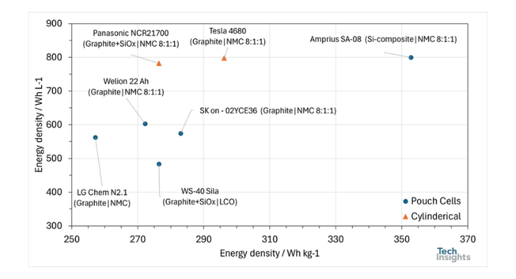
Figure 3: Comparison of volumetric and gravimetric energy densities of the Amprius SA-08 with the batteries of the Chevy Bolt (first generation), Tesla Model 3 (2019), Tesla Model Y (2022), Hyundai IONIQ 5 (2023), the Welion 22,000 mAh semi-solid-state battery, and the battery in the Whoop 4 (WS-40).
Electrochemical Characterizations
The electrochemical characteristics of the battery were assessed using differential capacity (dQ/dV vs. V) and electrochemical impedance spectroscopy.
Differential capacity analysis (DCA, dQ/dV) is a method that identifies regions in the voltage profile associated with the phase equilibrium of the active electrode material. The peaks in the DCA, caused by plateaus in the voltage profile, correspond to phase transitions in the active electrode material due to intercalation, which appear as flat regions in the voltage profile. We performed a C/40 charge-discharge test to infer the cell’s chemistry and minimize the effects of ohmic resistance, with the results plotted in Figure 4.
Figure 4 : Differential capacity analysis of the Amprius SA-08 at a rated current of C/40.
The DCA profile of the Amprius SA-08 shows several peaks in both the charge and discharge directions, with the peaks being not perfectly symmetric but close to a symmetrical shape, particularly at cell voltages above 3.4 V. A symmetrical shape usually indicates that the reactions are reversible (lithiation and delithiation of the anode and cathode), and that undesirable side reactions are minimized. According to the datasheet for the Amprius SA-08, the cathode in this battery is based on Nickel Manganese Cobalt Oxide (NMC) with a stoichiometric ratio of 8:1:1. To gain insights into the effect of using silicon instead of graphite, we compared the DCA profile of the Amprius SA-08 with the SK On-2YCE36 (the battery used in the Hyundai IONIQ 5), which uses graphite at the anode and NMC 8:1:1 at the cathode. In both cases, we normalized the dQ/dV values by dividing them by the cell capacity, as shown in Figure 4.
Figure 5: Comparison of differential capacity analysis of the Amprius SA-08 and SK on - 02YCE36 batteries. Both tests were performed at a rated current of C/40, and results are normalized based on their rated capacity.
As shown in Figure 4, the peaks in the case of the graphite-based anode are more symmetric, suggesting a longer cycle life. Although the peaks related to the (de-)lithiation of the cathode and anode are convoluted, the peak in the discharge direction around 3.3 V is specific to silicon. Compared to the SK On-2YCE36, the DCA profile of the Amprius SA-08 shows less pronounced fluctuations at cell voltages above 3.4 V. We believe this characteristic could help in designing a simpler fast-charging profile for this battery.
Electrochemical impedance spectroscopy (EIS) is a method used to characterize the kinetic and thermodynamic properties, interfacial reactions, and phase transitions in the electrochemical systems of batteries. The impedance and internal resistance of this battery were analyzed using EIS at different states of charge (SOC). EIS measurements were performed over a frequency range of 3 kHz to 50 mHz by applying a sinusoidal signal with a 10 mV amplitude. The corresponding results are presented in Figure 6 as a Nyquist plot.
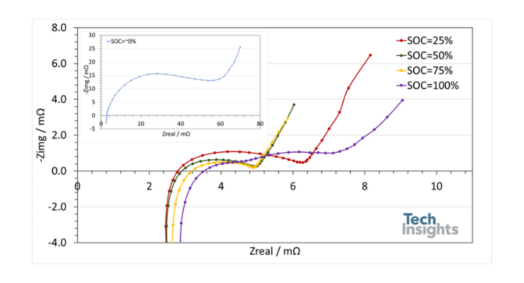
Figure 6: Nyquist diagram of electrochemical impedance spectroscopy of the Amprius SA-08 at different state of charges. The results at state of charge of 0% are shown as insert in the figure.
Generally, each spectrum consists of two overlapping semicircles (except at SOC = 100%, where the semicircles become separated) at high-to-medium frequencies, followed by a 45° line in the low-frequency region. The intersection of the real and imaginary axes indicates the overall ohmic resistance. The first semicircle represents the solid electrolyte interphase of the battery, while the second semicircle corresponds to the electrochemical reactions at the anode and cathode. At SOCs below 75%, the first and second semicircles have similar time constants, so only one semicircle is observed. As the battery charges, the time constants of the solid electrolyte interphase and electrochemical reactions change, making the second semicircle detectable. The 45° line corresponds to the diffusion of lithium ions.
A comparison of the spectra reveals that the battery impedance is highest when fully discharged and decreases as it charges to 50% SOC. Further charging slightly reduces the impedance. However, at 100% SOC, the battery impedance increases again. Except at 0% SOC, the battery exhibits an overall impedance of less than 8 mΩ, associated with ohmic resistance and transport phenomena in the battery.
At SOC = 0%, however, the battery shows significantly higher impedance—almost ten times greater. Typically, lithium-ion batteries exhibit about four times higher impedance when fully discharged. In the case of the Amprius SA-08, this effect is more pronounced despite the cell being optimized for power-based applications.
A comparison of Nyquist diagrams also shows that the ohmic resistance of the Amprius SA-08 (the intersection of the real and imaginary axes) increases from 2.7 mΩ to 3.5 mΩ (~31%) due to changes in the crystalline structure of the anode and cathode, as well as possible changes in the electrolyte's conductivity. While changes in the ohmic resistance of lithium-ion batteries as they charge have been reported before, in contrast to the Amprius SA-08, this change usually results in a reduction in ohmic resistance.
The unique features of the Amprius SA-08, including its energy density and power handling, are based on the cell's structural design and the materials used in its active components. Here, we briefly report on the characterization of the cathode and anode of the Amprius SA-08, while the detailed analysis can be found in the Battery Cell Essentials report titled (SA08-Amprius Silicon Anode Battery (Upgrade Energy -440W 32A battery pack)).
Material Characterization
To understand the chemistry of this battery, we opened a cell inside the glovebox in a discharged condition to collect samples for material characterization.
Cathode
Figure 7 shows the planar view of the cathode obtained using scanning electron microscopy (SEM) and an energy-dispersive results. The cathode is composed of NMC-based particles with an atomic ratio of 8:1:1, as confirmed by energy-dispersive spectroscopy (EDS), shown in Figure 7b.
The cathode also contains a polymer binder and a conductive additive. The primary function of the polymer binder is to hold together the active material and conductive additive, improving the mechanical stability, particle cohesion, and flexibility of the electrodes. The signals for carbon and phosphorus in the EDS diagram (Fig. 7b) originate from the polymer binder and conductive additive. Two polymer binders are commonly used for NMC-based cathodes: polyvinylidene fluoride (PVDF) and polytetrafluoroethylene (PTFE). PVDF is primarily used in wet electrode preparation when the active material is dissolved in solvents such as N-methyl pyrrolidone (NMP) and N,N-dimethylformamide (DMF), while PTFE is used for dry processing [7]. The exact identification of the binder type requires further investigation, such as through Fourier-transform infrared spectroscopy (FTIR) analysis.
Figure 7: a) planar SEM view and b) EDS results of the cathode of the Amprius SA-08.
Anode
Figure 8a shows the SEM planar view of the anode, while the detailed EDS results are shown in Figure 8b. The SEM image indicates that the anode is primarily (almost entirely) composed of silicon particles. However, the teardown analysis of the battery suggests that the silicon particles are coated with carbon, likely to improve the SEI (solid electrolyte interphase) layer properties. The carbon signal in the EDS results is not solely related to the carbon coating; it could also be associated with the polymer binder used in the battery, such as PVDF. In the case of a silicon-based anode, solvent-free dry electrodes using polytetrafluoroethylene (PTFE) as a binder are challenging, as silicon can scratch and damage the rollers required to compress the electrode dough and laminate the electrode onto the foil at very high pressure.
Figure 8: a) planar SEM view and b) EDS results of the anode of the Amprius SA-08.
Figures 9a and 9b show cross-sectional SEM images and an SEM map of a single anode electrode from the Amprius SA-08, consisting of a copper current collector double-coated with the active materials. These images show the presence of silicon particles in the depth of the anode's active layer. However, the images are inconclusive regarding the use of silicon nanowires in the anode. Although these images resemble silicon particles, we plan to conduct more detailed SEM analysis for further investigation. This analysis will help determine whether SiCore™ by Amprius is entirely different from the Silicon Nanowire Platform (SiMaxx™).
Figure 9: a) Cross-section SEM view and b) EDS map of an anode of the Amprius SA-08.
Additionally, we plan to perform X-ray Photoelectron Spectroscopy (XPS) to determine the oxidation state of the silicon-based particles. To identify the type of carbon-based material used in the anode, we also plan to conduct Raman Spectroscopy. Both XPS and Raman Spectroscopy results will be included in our report.
Electrolyte and Separator
The most common electrolyte for lithium-ion batteries is a solution of lithium hexafluorophosphate (LiPF6) in a carbonate-based solvent due to its high conductivity and thermal stability. However, LiPF6 is prone to forming HF, which can etch silicon-based materials. As a result, lithium bis(trifluoromethanesulfonyl)imide (LiFSI) and lithium difluoro(oxalate)borate (LiDFOB) are considered promising alternative salts for Li-ion batteries with silicon-based anodes [8].
The electrolyte formulation of the Amprius SA-08 (including salts and solvents) will be analyzed by TechInsights, and the results will be available in our report.
Additionally, our report will provide details on the separator used in the Amprius SA-08 battery. Lithium-ion batteries with silicon-based anodes generally do not require significant changes to the separator design. However, the significant volumetric changes during charge and discharge must be considered in the cell design to ensure that the separators do not fold during battery operation.
Silicon based anode batteries as future battery technology
Figure 1 shows that silicon composite-based anode batteries and solid state batteries with lithium anodes outperform other battery technologies in terms of energy density, except for lithium metal batteries. However, it should be noted that lithium metal batteries are considered unsafe due to the presence of lithium metal and liquid electrolyte. For example, the implementation of current lithium metal battery technology in EVs could potentially lead to battery explosions in the event of a car collision. Therefore, lithium metal batteries need improvements not only to suppress dendrite formation at the anode during charging but also to enhance overall battery safety.
Excluding lithium metal battery technology, silicon-based anodes are the most promising for developing high-energy-density cells because solid state batteries with lithium anodes needs generally need applied pressure system which reduces their energy density. Our analysis shows that such cells, like the Amprius SA-08, are currently entering the market. These batteries not only offer high energy density but also demonstrate strong power handling, as indicated by the DCA profile (Figures 4 and 5).
Despite their significant advantages over graphite-based lithium-ion batteries, silicon composite-based anodes still suffer from short cycle life, as discussed in the electrochemical characterization section. If a silicon composite-based anode is discharged to only 70% of its depth of discharge, its energy density becomes similar to that of lithium-ion batteries. For example, in the case of the Amprius SA-08, the volumetric and gravimetric energy densities drop to 700 Wh/L and 245 Wh/kg, respectively, comparable to power-based lithium-ion batteries.
One approach to extend the cycle life of silicon composites while benefiting from their high energy density is to develop smart charge-discharge algorithms that operate the battery in optimized states of charge and use the full capacity only when necessary. These types of algorithms are already widely used in laptops. Our battery supplement reports (BCS Report codes) provide details on algorithms that extend the cycle life of batteries.
The results and analysis show that while silicon composite anode technology needs further development to improve cycle life, the current technology is suitable for batteries in devices with limited lifespans, such as drones. However, its application in consumer electronics and EVs requires additional advancements. Therefore, the competition between silicon composite anodes and lithium metal-based solid-state batteries is still ongoing. We are actively monitoring the market for upcoming silicon composite anode and solid-state batteries.
References
- Li, Yifei, et al. "Si-based anode lithium-ion batteries: A comprehensive review of recent progress." ACS Materials Letters 5.11 (2023): 2948-2970.
- The Battery Report 2023.” Volta Foundation, X January 2024. https://volta.foundation/battery-report. (assessed 5 September 2024)
- Frith, James T., Matthew J. Lacey, and Ulderico Ulissi. "A non-academic perspective on the future of lithium-based batteries." Nature Communications 14.1 (2023): 420.
- Schmaltz, Thomas, et al. "A Roadmap for Solid‐State Batteries." Advanced Energy Materials 13.43 (2023): 2301886.
- Amprius Broadens Product Portfolio with New Commercially Available Silicon Anode Battery Platform – SiCoreTM, January 2024, https://amprius.com/amprius-broadens-product-portfolio-with-new-commercially-available-silicon-anode-battery-platform-sicoretm/ (assessed 5 September 2024)
- Data sheet of Pouch cell - Amprius SA08 High Power "Black Series" 360Wh/kg, Upgradeenergy.com, https://ebd994b0-7ab0-4123-bf06-f30fe62c41b1.usrfiles.com/ugd/ebd994_e801d6ad8ca744ab8a7da9fce5d149ce.pdf (assessed 5 September 2024).
- Wei, Ziqi, et al. "Removing electrochemical constraints on polytetrafluoroethylene as dry-process binder for high-loading graphite anodes." Joule 8.5 (2024): 1350-1363.
- Xu, Zhixin, et al. "Electrolytes for advanced lithium ion batteries using silicon-based anodes." Journal of Materials Chemistry A 7.16 (2019): 9432-9446.


