Graphene or not? Investigating the Panasonic NCR 21700 powering the Tesla Model 3 and Chargeasap Power bank

Dr. Ali Khazaeli
Panasonic is one of the top five Li-ion battery manufacturers worldwide [1]. In partnership with Tesla, they built the Gigafactory facilities in Nevada [2]and designed the NCR 21700 batteries for the Model 3 electric vehicle (EV). This cell benefits from a 5% improvement in energy density and by increasing nickel content in the cathodic material, namely (NCA: Lithium Nickel-Cobalt-Aluminum Oxide (LiNixCoyAlzO2)) and introducing silicon in the anode [3].
Panasonic NCR 21700 and the Tesla model 3:
The NCR 21700 battery was designed to improve the power and energy densities beyond what is available with the Panasonic PAN BD 18650 cells [4]. Although NCA cells theoretically provide similar energy density and power density to Lithium-Nickel-Manganese-Cobalt-Oxide (NMC) based cells, their fast charging is more challenging due to the oxide layer formation at the cathode during discharge, increasing the battery's impedance. To overcome this issue, Tesla designed a heating management system to warm up the cells to a specific temperature before fast charging. This method can reduce the charging time to ~ 80 minutes without compromising the cyclic life of the battery.
Panasonic NCR 21700 and the Chargeasap FLA201G 210 W Power bank:
Chargeasap is a Sidney, Australia-based startup that aims to create innovative charging accessories for mobile devices. They typically launch their products through a crowdfunding process. Interestingly, the Chargeasap FLA201G power bank uses four Panasonic NCR 21700 batteries. Chargeasap claims that these NCR 21700 cells benefit from graphene technology leading to a full charge in just 70 minutes (20,000 mAh) or 80% charge (16,000 mAh) in only 35 minutes. The controversial aspect of Chargeasap’s claims is Tesla never mentions the application of graphene in any of their NCR 21700 descriptions. With the amount of interest in Tesla and the NCR 217000 cell, TechInsights wanted to get to the bottom of this mystery and understand the underlying technology of this battery.
Reverse Engineering the FLA201G Power Bank
We opened the Chargeasap FLA201G power bank and found that the battery pack consists of four Panasonic NCR 21700 in series (4S). Figure 1 shows the inside of the device along with its batteries.
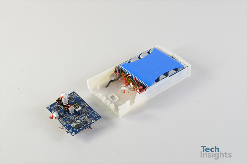
Figure 1: Inside the FLA201G power bank.
Battery Cells
The cells are cylindrical shaped (70.5 mm long and 21.1 mm in diameter) with a capacity of 4800mAh with an average cell voltage of 3.7 V
Figure 2 shows an individual cell used in the FLA201G 210 W Power bank.
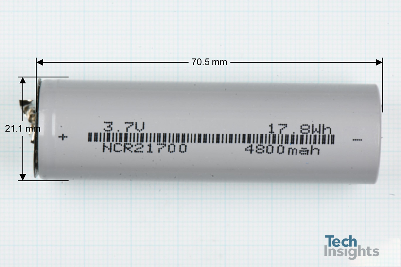
Figure 2: Individual cylindrical cells used in a FLA201G power bank.
Battery Materials
Different components of the battery were characterized using various methods, including Scanning Electron Microscopy (SEM) coupled with Energy-dispersive X-ray spectroscopy (EDX) at different locations and magnification, FTIR (Fourier transform infrared), and Raman spectroscopy. Looking deeper into the cell structure (Figure 3) we see the cell jellyroll is comprised of ~165 µm thick layers, including the aluminum current collector, the cathodic material, the polymeric separator, the anodic material, and the copper current collector [6].
As expected, the cathodic active material is Lithium Nickel-Cobalt-Aluminum Oxide, as confirmed by our Energy-dispersive X-ray spectroscopy (EDX) test's results. The anode is formed with graphite containing embedded silicon oxide (SiOx or SiO) particles. Incorporating SiO increases the battery's capacity by forming lithium silicides, which can bind four lithium ions for every silicon atom. Theoretically, "Silicon anodes can store ten times as much charge in a given volume than graphite anodes -- a whole order of magnitude higher in energy density" [5].
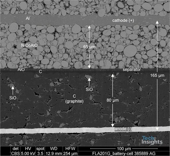
Figure 3: Detailed SEM Cross Section of the jellyroll.
Presence of graphene in the anode active materials
The presence of graphene is evaluated by Raman spectroscopy by taking samples from 3 different parts of the anode jellyroll (beginning, middle and endpoint), and the results are plotted in Figure 4. Analyzing the spectra reveals that no graphene is used in the anode of this battery as an additive, and the Raman spectrum is well-matched with ball-milled graphite. Now, a question arises why Chargeasap claimed the presence of graphene in this battery. This could be attributed to the fact that Ball-milled graphite features a similar Raman spectrum to that of graphene nanoplatelets. To better understand this statement, we need to get insight into the Raman spectroscopy of graphite and graphene. Raman spectra of graphene include three main bands, namely, Figure 4, the G-band, the D-band, and the 2D-band. These bands are indicative of the number of layers of graphene present and the quality of the sample. G-band and 2D-band will always be present. However, the D-band will only be seen for samples containing defects for both graphene and graphite. The 2D band provides conclusive information regarding the presence of graphene [7,8].

Figure 4: Raman Spectroscopy of the anode of Panasonic NCR 21700.
In the case of pure graphene, the 2D band situated at ~2700 cm−1 is a sharp and symmetrical peak. Whilst in the Raman spectrum of graphite, the 2D band is formed from two elements leading to an asymmetric peak. This peak evolution is due to the fact that graphite is a multi-stacked layer of graphene. As the number of graphene layers increases to about ten layers, the profile resembles that of graphite [7,8]. Additionally, in the case of pure graphene, the intensity of the 2D band would be higher than that of the G band.
Figure 4 shows that the 2D band slightly deviates from a symmetrical shape indicating a stacked layer of graphene (almost 5 layers). However, the intensity of the 2D band is significantly lower than G-band. In the case of pure graphene, the intensity of the 2D band would be higher than that of the G band.
The existence of the D-band suggests some defects in the particles, indicating the process of ball-milling during battery manufacturing. Ball-milled graphite or ‘nano graphite’ consists of spherical particles containing highly defective crystalline structure as a direct consequence of ball milling. These structures have been named graphene nanoplatelets or multi-layer graphene in literature. However, a long process of ball-milling (24 hr.) leads to a significant exfoliation of graphene nanoplatelets from the graphite. In the case of NCR 21700, the ball-milling process is estimated to be around 12 hr., leading to a marginal exfoliation of the graphite and the formation of graphene nanoplatelets (GNP) [9]. Therefore, the existence of a fraction of GNPs should not be mistaken by the application of graphene (like reduced graphene oxide) as an additive in the anode of lithium-ion batteries.
To see a practical example of a significant amount of graphene added to the anode to substantially improve the power density of a Li-ion battery, please refer to our recent report entitled “LPR Graphene-4 graphene-enhanced anode LiPo (RC car pack)” in our Battery Essentials channel [10].
For additional information on the Panasonic NCR 21700 cell including active materials (NCA and Graphite), the existence of dopant particles, separators, and electrolyte components, please see the full report entitled “Panasonic NCR 21700 LIB (Chargeasap)” [6].
References
- “A Look At The Top 5 Lithium-Ion Battery Manufacturers In 2019,” Seeking Alpha
- “Tesla Gigafactory”
- “Panasonic boosts energy density, trims cobalt in new 2170 battery cell for Tesla,” TechCrunch
- “All Things You Need to Know about 21700 Battery,” DNK Power
- "Silicon anode structure generates new potential for lithium-ion batteries,” ScienceDaily
- Application Note: Raman Microscopy of Graphene.
- Bîru, Elena Iuliana, and Horia Iovu. "Graphene nanocomposites studied by Raman spectroscopy." Raman Spectrosc 9 (2018): 179.
- Kaniyoor, Adarsh, and Sundara Ramaprabhu. "A Raman spectroscopic investigation of graphite oxide derived graphene." Aip Advances 2.3 (2012): 032183.


